Under-display cameras using active sensing
It is of interest within the industry to make a device with the camera placed behind the display for several reasons. It would allow for a cleaner industrial design that does not require camera windows or notches; it would allow the display to cover the full surface of the device; and it would provide better video conferencing due to the camera capturing from nearer where the user is looking.
However, imaging through the display requires overcoming two conflicting goals. On the one hand, the display needs to show a bright, high-quality image. On the other hand, enough light must pass through the display uninterrupted in the opposite direction for the camera to record. The more you optimize the design for one of these goals, the more the quality of the other tends to suffer.
Other work on the team investigated trying to address this conflict using machine learning. However, for some displays, parts of the scene cannot be faithfully recovered by a machine-learning algorithm because too much information would be missing in the captured image. Although a good machine-learning algorithm might produce a plausible reconstruction, for some applications (such as biometrics) it is essential that the image be derived from true, and not synthetic, data. To address this need, this project investigates an optical hardware-based method of through-display image recovery.
The problem of imaging through a display can be visualized by looking at a close-up of an example display that would be placed in front of the camera:

The picture above shows a 3×3 patch of pixels of a 4K-resolution transparent OLED display. Even though this display is designed to allow light through, less than 20% of the area shown is open to allow that (the white areas). In addition, the shape and size of these openings block sets of rays from the scene so that the image captured with a typical camera would be blurry and even worse, completely missing some spatial frequencies.
This can be seen by examining the modulation-transfer functions (MTF) of screens with progressively narrower open areas. The narrower the pixel opening, the more the valleys of the MTF curve are truncated:
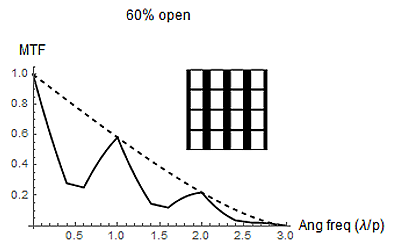
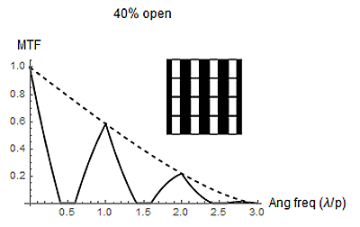
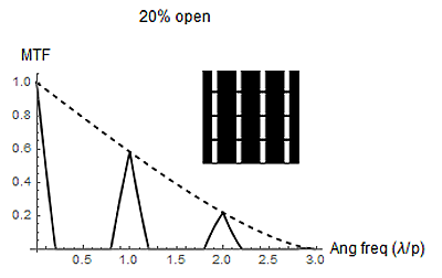
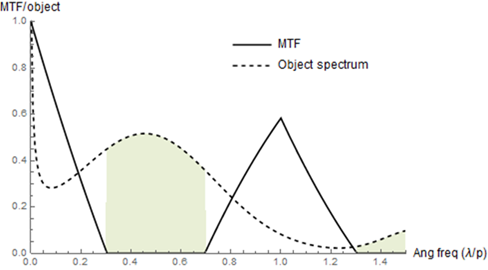
This is a problem. Because we are completely missing some spatial frequencies, we cannot even play computational tricks to boost them or otherwise recover the image after it has been captured. Imagine that we were trying to photograph a person wearing a striped shirt. If we couldn’t see stripes of that width, then in the photograph the shirt (ignoring other distortions) would look like a plain solid shirt. We would have no way to know, from the captured image, whether the shirt was solid or striped—nor even whether something was missing.
The process
To try to “fill in” these missing frequencies that the camera can’t see because they are blocked by the display, we investigated whether the problematic frequencies could be somehow translated within the scene (outside of the device and before reaching the display) into a different frequency range that the display does not block, so that the translated frequencies could pass through the display and be captured by the camera. In this work, we performed this translation by projecting a pattern onto the scene that would produce a moiré effect with the spatial frequencies already there such that information about the frequencies the camera cannot see are contained within the frequencies of the moiré pattern, and the moiré’s frequencies are within the range that can reach the camera.
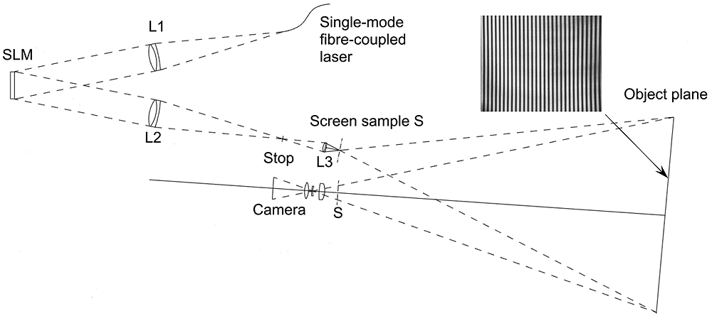
However, we cannot simply project the pattern from in front of the display. After all, if the motivation for this work is to remove the camera from in front of the display, it would make no sense to replace it with another component—a light source—in the same place. Nor can the pattern simply be projected from behind the display either, for the required pattern itself also contains frequencies that the display would block as it left the device. So, instead, the team produced the pattern from behind the display by creating two coherent point sources positioned within one display pixel (about 80 microns apart). The light from these sources interferes at the scene, and the resulting sinusoidal interference pattern aliases the problematic spatial frequencies within the scene to a lower range which can pass through the display and be captured by the camera.
However, once the scene is illuminated this way, the camera will see these lower spatial frequencies (which are from the moiré but not really in the scene) simultaneously with the real frequencies from objects in the scene that just happen to be at the same lower frequencies as the aliased frequencies. To disentangle these frequencies so as to shift the altered frequencies back to what they originally were in the scene, the scene is imaged three times with different phase relationships between the point sources. This provides enough information to recover the original frequencies.
A more detailed discussion of the recovery process can be found in the linked publication.
The results
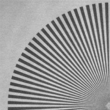
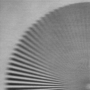
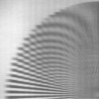
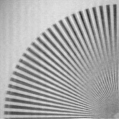
We can demonstrate the results by starting with a scene of a radial spoke pattern designed to have details at multiple spatial frequencies:
Related projects
- Under-Display Camera with Machine Learning
- Camera in Display: Machine Learning and Embedded Cameras Make Possible a New Class of More Natural Videoconferencing Devices